

Introduction
We have introduced the overview and simple functions of LTspice in article Try LTspice – Intro.
In this article, I will show you how to get started with LTspice and how to operate it in a simple circuit design.
Circuit design
Now let’s start designing circuits with LTspice.
This time, we will make a step-down circuit using the LT 3045 (linear regulator) of the former Linear Technology product.
Design with reference to the circuit shown below on the top page of the data sheet.
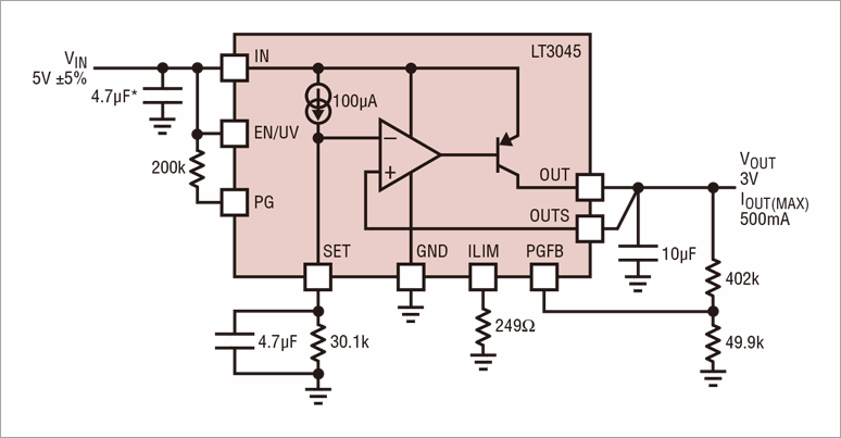
Reference circuit
Begin with a new schematic
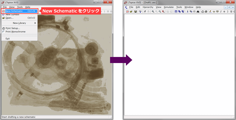
1. Click File > New Schematic to display a blank layout screen.
2. Start circuit design
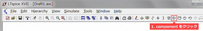
Place ICs and Parts
1. Click component and enter "LT 3045". If it is selected, click the OK button.
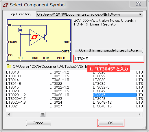
Select Component Symbol (LT3045)
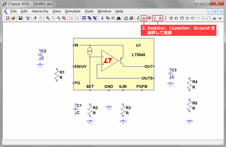
2. Select Resistor, Capacitor, and Ground from the toolbar and arrange them as shown below.
(These can be rotated with Ctrl + R)
3. Click component again and enter "voltage" to place the Voltage Source in the circuit.
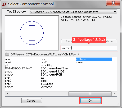
Select Component Symbol (voltage)
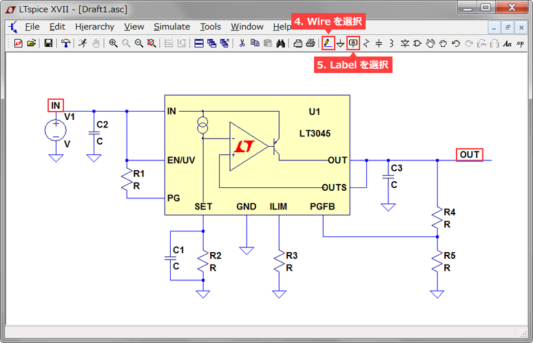
4. Select Wire from the toolbar to wire the circuit.
5. Select Label from the toolbar and name the input and output nodes "IN" and "OUT".
There are 2 merits of attaching a label.
- Unlike the node name inside SPICE, the waveform name is easy for people to understand (on the simulation result screen).
- Node names with the same name have the same potential, so they are connected without wiring in the case of a complicated circuit configuration.
Add wires and labels
Part Parameter Selection
1. Right-click R, C, and voltage source (V1) and change their values.
((You can edit it by holding the mouse over the part you want to change and right-clicking.)
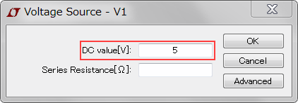
Select Applied Voltage
2.From the part library, select the part you want to use, if any. You can open the part library by selecting "Select Capacitor" or "Select Resistor" on the parameter selection screen.
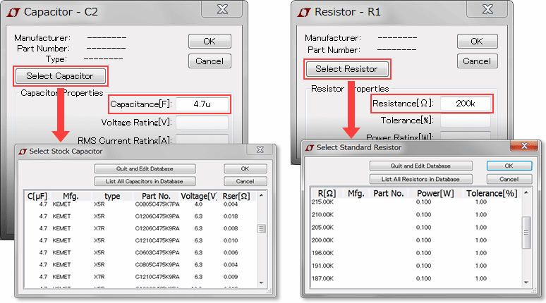
Part parameter selection and library
※Notes
The unit label on LTspice is the same as the International System of Units, but note the following 3 points.
- 10^6 uses MEG (meg) instead of M (m).
- For 1 farads, just type 1, not 1F.
- μ for 10^- 6 is entered as "u" on LTspice.
Execution of simulation
Now that the design of the circuit diagram has been completed, the simulation will be executed.
The simulation will be executed by the following procedure.
1. Click the Run button from the toolbar to display the "Edit Simulation Command"
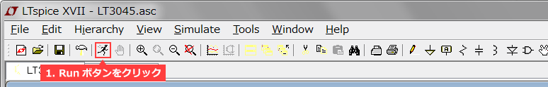
GUI (Run)
2. Set the "Stop time" here (5 msec here) and click OK to start the simulation.
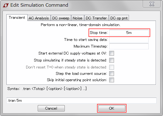
Edit Simulation Command (Stop time)
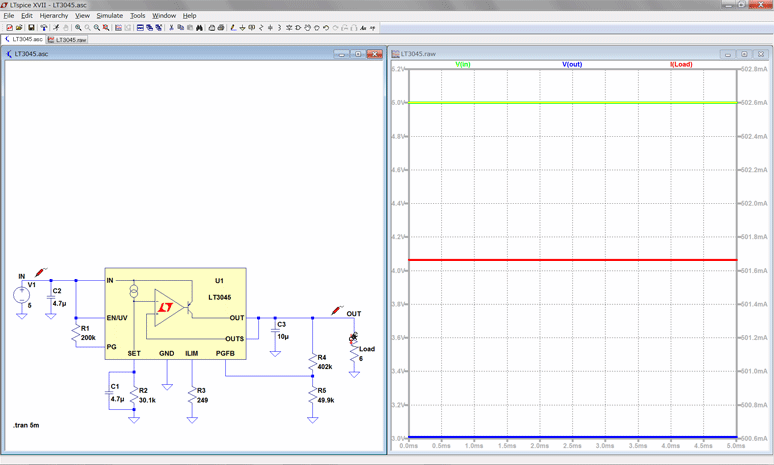
3. Click the part you want to observe in the waveform viewer
It was confirmed that the designed output voltage was 5V, the output voltage was approximately 3V, and the output current was approximately 500 mA.
 Execution of simulation
Bonus
The above procedure was followed to create a circuit for the standard application on the top page of the data sheet.
However, there is a convenient function of the LTspice as a test circuit.
Note the screen where LT 3045 is selected from Component in step 1 of "IC and Component Placement". The "Open this macromodel's test fixture" button is above the input.
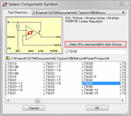
Selection of test circuit
By clicking here, the test circuit that is prepared as shown below will be output.
(Note that some ICs are not prepared.)
With a test circuit, you can run a simulation by simply clicking the Run button.
You can change the condition only by changing the parameter of the peripheral part.
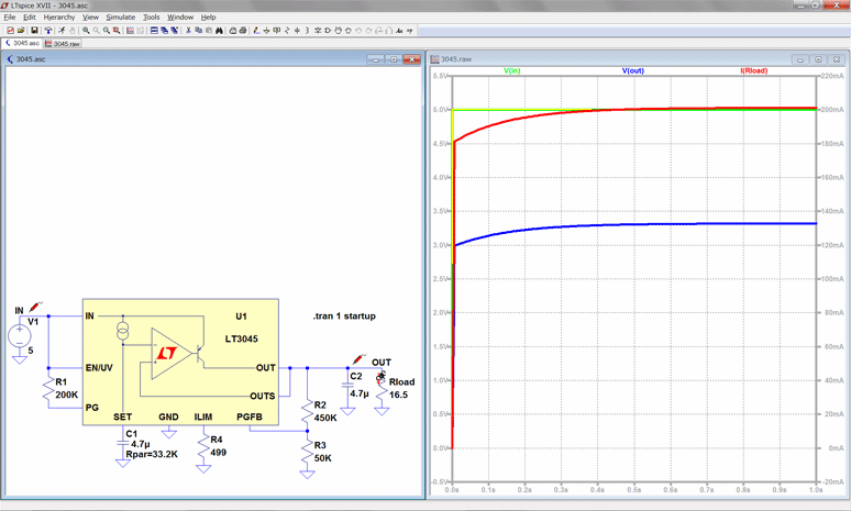
Simulation of the test circuit
Summary
How was the circuit design using LTspice.
As described above, the circuit design can be performed by simple operation, so that the characteristics can be checked easily.
In addition, since it is easy to change the parameter of the peripheral constant, it is the best tool for the characteristic confirmation before the substrate is produced.
LTspice excels other tools in the accuracy of the simulation as well as the ease of use.
Why won’t you have try.