

In this article, let’s try making a variable resistor.
When performing a circuit simulation, you may want to change the resistance value and check the movement of the node voltage and current. However, LTspice does not have a component element like a variable resistor that changes the resistance.
This time, I will show you how to change the resistance.
- Set the resistance parameter with the voltage source
Normally, LTspice sets the resistance element parameter to a constant such as R = 10Ω. However, it can be set by R = <expression>, and the resistance value can be changed by specifying the node voltage in <expression>.
run a simulation immediately. In this case, the resistance value is varied from 1k to 10k.
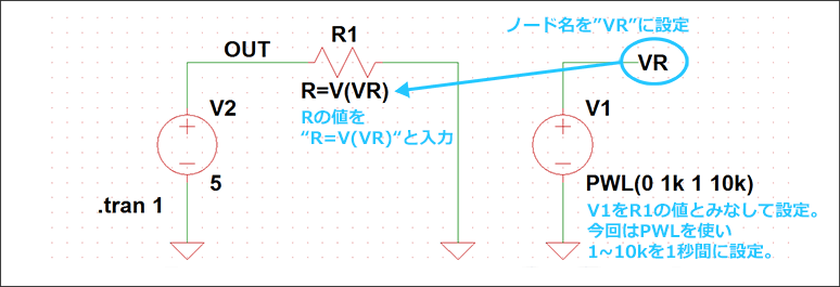
The completed circuit diagram and preparation procedure are as follows.
- Prepare voltage source V1 and set the node voltage. Here, the node is referred to as "VR".
- The voltage value of the voltage source V1 is assumed to be the resistance value. In this case, the voltage source is set to PWL (0 1k 1 10k) in order to change the slope from 1k to 10k in 1 seconds.
- Set the value of resistor R1 to R = V(VR).
- Run the simulation by applying voltage source V2 (here, 5V) to the Tran analysis setup and resistance.
Set the node voltage to the resistance parameter
By setting V (out)/I(R1) from "Add Trace" on the viewer of the simulation result as shown below, the resistance was variable with respect to the time axis and the simulation was executed.
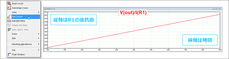
Resistance of R1
With this method, you can change the resistance value in the Tran analysis (time analysis), so you can see the voltage and current changes as the resistance changes.
- .Creating Variable Resistance Using OP Analysis
Voltage divider using a variable resistor
Although we used the Tran analysis earlier, we will show you how to change the resistance value using the. OP analysis (operating point analysis).
In this method, you can change the resistance value using the ".step" command and check the node voltage and current.
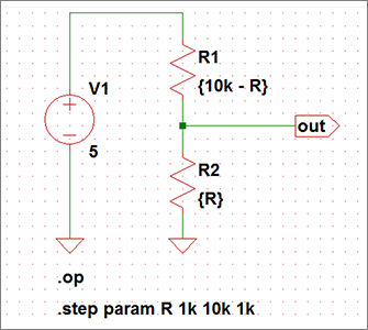
Here, the resistors R1 and R2 are regarded as variable resistors, and the divided node voltage is simulated when the DC voltage source is connected.
As shown in the circuit diagram below, the resistor parameters are changed every 1kΩ between the variable 'R' and 1kΩ and 10kΩ using the .step command.
The simulation results are shown below.
The horizontal axis is the changed resistance value, and the vertical axis is the voltage value divided from the variable resistor.
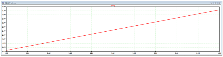
Voltage value when the resistance value is changed
Thus, the voltage node change can be easily confirmed by the .step command and .OP analysis.
- The LTspice demo file we examined
You can download LTspice from below URL link.
https://www.analog.com/en/design-center/design-tools-and-calculators/ltspice-simulator.html